Showing posts with label Sound Design. Show all posts

Wednesday, July 6, 2016

Chip tunes - Part 1 History and evolution

A sound chip is an integrated circuit (i.e. "chip") designed to produce sound. It might be doing this through digital, analog or mixed-mode electronics. Sound chips normally contain things like oscillators, envelope controllers, samplers, filters and amplifiers. During the late 20th century, sound chips were widely used in arcade game system boards, video game consoles, home computers, and PC sound cards.

Chiptune refers to a collection of related music production and performance practices sharing a history with video game soundtracks. The evolution of early chiptune music tells an alternate narrative about the hardware, software, and social practices of personal computing in the 1980s and 1990s. By digging into the interviews, text files, and dispersed ephemera that have made their way to the Web, we identify some of the common folk-historical threads among the commercial, noncommercial, and ambiguously commercial producers of chiptunes with an eye toward the present-day confusion surrounding the term chiptune.

In its strictest use, the term chiptunes refers to music composed for the microchip-based audio hardware of early home computers and gaming consoles. The best of these chips exposed a sophisticated polyphonic synthesizer to composers who were willing to learn to program them. By experimenting with the chips' oscillating voices and noise generator, chiptunes artists in the 1980s—many of them creating music for video games—developed a rich palette of sounds with which to emulate popular styles like heavy metal, techno, ragtime, and (for lack of a better term) Western classical. Born out of technical limitation, their soaring flutelike melodies, buzzing square wave bass, rapid arpeggios, and noisy gated percussion eventually came to define a style of its own, which is being called forth by today's pop composers as a matter of preference rather than necessity.

The earliest precursors to chip music can be found in the early history of computer music. In 1951, the computers CSIRAC and Ferranti Mark 1 were used to perform real-time synthesized digital music in public. One of the earliest commercial computer music albums came from the First Philadelphia Computer Music Festival, held August 25, 1978, as part of the Personal Computing '78 show. The First Philadelphia Computer Music Festival recordings were published by Creative Computing in 1979. The Global TV program Science International (1976-9) credited a PDP-11/10 for the music.

CSIRAC
CSIRAC Computer

Ferranti Mark 1
Ferranti Mark 1 Computer


Before the appearance of microcomputers at the end of the 1970s, digital arcade games provided the primary computing experience for people outside of financial data centers, university labs, and military research facilities. Installed in loud public spaces like bars and roller-skating rinks, the experience of playing these games was likely accompanied by the sound of a nearby radio, DJ, or jukebox playing the latest disco and progressive rock. In the early 1980s, computer gaming followed computers into the privacy of the home. The sound produced by arcade cabinets might have competed with other environmental noises, but many of the earliest home computer games included only a brief theme, a few sound effects, or no sound at all. The general-purpose home platforms were not as well suited to audio reproduction as the custom-built arcade cabinets. Nevertheless, during the first few years of the 1980s, the number of platforms diversified, and each new design provided a different set of affordances for the growing number of computer music composers to explore.

The Apple II home computer, released in 1977, included a single speaker inside of its case that could be programmed to play simple musical phrases or sound effects (Weyhrich 2008). In-game music was very rare as memory storage for audio data was limited and audio playback was costly in terms of the central processing unit (CPU) cycles (note 1). The Atari VCS game console, released the same year as the Apple II, was designed to be attached to a television. Its television interface adapter (TIA) controlled both the audio and video output signal.


Steve Jobs demonstrating the Apple II 

Atari 2600 VCS


Although the TIA could produce two voices simultaneously, it was notoriously difficult to tune (Slocum 2003). Rather than include multivoice harmonic passages for a machine with unpredictable playback capacity, games such as Atari's Missile Command implemented rhythmic themes using controlled bursts of noise for percussion instruments (Fulop 1981). Programmers charged with interpreting recognizable musical themes from arcade games, films, or pop groups were less free to experiment. Data Age's Journey Escape (1982), billed as "the first rock video game," struggled against the tonal limitations of the TIA in its squeaky interpretation of Journey's hit song "Don't Stop Believing," while Atari's E.T.: The Extra-Terrestrial (1982) presented a harmonically accurate re-creation of the original theme.


Example of Missle Command gameplay and sounds (Atari 1981)


Theme from journey escape (Data Age 1982)


Theme from Atari's E.T.: The Extra-Terrestrial (Atari 1982).


Continuous music was, if not fully introduced, then arguably foreshadowed as one of the prominent features of future video games as early as 1978, when sound was used to keep a regular beat in a few popular games. Space Invaders (Midway, 1978) set an important precedent for continuous music with a descending four tone loop of marching alien feet that sped up as the game progressed. Arguably Space invaders and Asteroids (Atari 1979, with a two-note “melody”) represent the first examples of continuous m music in games, depending on how one defines music. Music was slow to develop because it was difficult and time consuming to program on the early machines as Nintendo composer Hirokazu “Hip” Tanaka explains: “Most music and sound in the arcade era (Donkey Kong and Mario Brothers) was designed little by little, by combining transistors, condensers and resistance. And sometimes music and sound were even created directly into the CPU port by writing 1s and 0s, and outputting the wave that becomes sound at the end. In the era when ROM capacities were only 1k or 2k, you had to create all the tools by yourself. The switches that manifest dresses and data were placed side by side, so you have to write something like ‘1, 0, 0, 0, 1’ literally by hand. A combination of the arcade’s environment and the difficulty producing sounds led to the primacy of sound effects over the music in this early stage of game audio’s history.


Donkey Kong sounds and gameplay (Nintendo 1981)

By 1980, arcade manufacturers included dedicated sound chips known as programmable sound generators or PSGs into their circuit boards, and more tonal background music and elaborate sound effects developed. Some of the earliest examples of repeating musical loops in games were found in Rally X (Namco/Midway, 1980) which had a six bar loop (one bar repeated four times, followed by the same melody transposed to a lower pitch), and Carnival (Sega 1980, which used Juventino Rosas’ “Over the Waves” (waltz of ca 1889). Although Rally X relied on sampled sound using a digital to analog converter, Carnival used the most popular of early PSG sound chips, the General Instruments AY-3-8910. As with most PSG sound chips, the AY series was capable of playing three simultaneous square-wave tones, as well as white noise. Although many early sound chips had this four channel functionality, the range of notes available varied considerably from chip to chip, set by what was known as a tone register of frequency divider. In this case the register was 12-bit, meaning it would allow for 4,096 notes. The instrument sound was set by an envelope generator, manipulating the attack, decay sustain and release (ADSR) of a sound wave, by adjusting the ADSR, a sound amplitude and filter cutoff could be set.

AY-3-8910 Sound Chip


Gameplay and music from Carnival (Sega 1980)

Despite (or perhaps because of) the challenges presented, some developers embraced the limitations of these early home computing platforms. In preparation for the development of Activision's Pressure Cooker in 1983, Garry Kitchen determined a set of pitches that the Atari TIA could reliably reproduce. He then hired a professional jingle writer to compose theme music using only the available pitches. The resulting song is heard playing in two-part harmony on both TIA audio channels during the title screen. Pressure Cooker further challenged the audio conventions of the Atari VCS by including a nonstop soundtrack during game play. One of the TIA's voices repeats a simple, two-bar bass line, while the other is free to produce sound effects in response to in-game events.


Title screen and game play from Pressure Cooker (Activision 1983).


The Atari 8-bit family is a series of 8-bit home computers introduced by Atari, Inc. in 1979 and manufactured until 1992. All are based on the MOS Technology 6502 CPU running at 1.79 MHz, roughly twice that of similar designs, and were the first home computers designed with custom co-processor chips. This architecture allowed the Atari designs to offer graphics and sound capabilities that were more advanced than contemporary machines like the Apple II or Commodore PET, and gaming on the platform was a major draw; Star Raiders is widely considered the platform's killer app. Another computer with custom graphics hardware and similar performance would not appear until the Commodore 64 in 1982.


Atari 800
Atari 800 8 bit Computer

The Pot Keyboard Integrated Circuit (POKEY) is a digital I/O chip found in the Atari 8-bit family of home computers and many arcade games in the 1980s. It was commonly used to sample (ADC) potentiometers (such as game paddles) and scan matrices of switches (such as a computer keyboard). POKEY is also well known for its sound effect and music generation capabilities, producing a distinctive square wave sound popular among chip tune aficionados. The LSI chip has 40 pins and is identified as C012294. POKEY was designed by Atari employee Doug Neubauer, who also programmed the original Star Raiders.

Some of Atari's arcade systems use multi-core versions with 2 or 4 POKEY chips in a single package for more sound voices. The Atari 7800 allows a game cartridge to contain a POKEY, providing better sound than the system's audio chip. Only two games make use of this: the ports of Ballblazer and Commando.


This awesome 8 bit composition shows the power behind the POKEY sound chip.


Compilation of demos showing the Atari's 8 bit computers audio and video capabilities


The USPTO granted U.S. Patent 4,314,236 to Atari on February 2, 1982 for an "Apparatus for producing a plurality of audio sound effects. This referred to POKEY's sound generation abilities. The inventors listed were Steven T. Mayer and Ronald E. Milner.

No longer manufactured, POKEY is now emulated in software by classic arcade and Atari 8-bit emulators and with the SAP player.

In 1980, most home computer music remained limited to single-voice melodies and lacked dynamic range. Robert "Bob" Yannes, a self-described "electronic music hobbyist," saw the sound hardware in first-generation microcomputers as "primitive" and suggested that they had been "designed by people who knew nothing about music" (Yannes 1996). In 1981, he began to design a new audio chip for MOS Technology called the SID (Sound Interface Device). In contrast to the kludgy Atari TIA, Yannes intended the SID to be as useful in professional synthesizers as it would be in microcomputers. Later that year, Commodore decided to include MOS Technology's new SID alongside a dedicated graphics chip in its next microcomputer, the Commodore 64. Unlike the Atari architecture, in which a single piece of hardware controlled both audio and video output, the Commodore machine afforded programmers greater flexibility in their implementation of graphics and sound.

SID (Sound Interface Device) 6581
SID (Sound Interface Device) 6581 Chip used in C64 computers

Technically, the SID enables a broad sonic palette at a low cost to the attendant CPU by implementing common synthesizer features in hardware. The chip consists of three oscillators, each capable of producing four different waveforms—square, triangle, sawtooth, and noise (note 3). The output of each oscillator is then passed through an envelope generator to vary the timbre of the sound from short plucks to long, droning notes. A variety of modulation effects may be applied to the sounds by the use of a set of programmable filters to create, for example, the ringing sounds of bells or chimes.


Commodore C64 Sid Collection

Several peripherals and cartridges were developed to take advantage of the music-making possibilities of the Commodore 64's SID chip, but even the best of these products could not match the flexibility and freedom of working with the chip's features directly by writing programs in 6502 assembly language (Pickens and Clark 2001). Of course, although the SID's implementation of sound synthesis would be familiar to electronic musicians of the time, programming in assembly was a very different experience from turning the knobs and sliding the faders of a comparable commercial synthesizer like the Roland Juno-6. Early Commodore 64 composers had to write not only the music, but also the software to play it back.

In the mid-1980s, chiptunes and computer game music appeared largely indistinguishable. The game music was not distinct from the rest of pop music, however: the songs reflected the musical interests of their composers. Most of the composers discussed here were young men living in Europe and the United States, and the influence of heavy metal, electro, New Wave pop, and progressive rock were prevalent throughout the 1980s. By assigning a distinct timbre to each of the voices, the SID could emulate the conventional instrumentation of a four-piece rock band: drums, guitar, bass, and voice (Collins 2006). For example, Martin Galway's 11-minute title track for Origin System's Times of Lore (1988) reflects the influence of classical guitar in heavy metal. Like the opening section of Metallica's "Fade to Black" from 1984, Times of Lore begins with an arpeggiated chord progression played on one voice with a harmonized "guitar solo" layered on top using a second voice.


Theme from Origin System's Times of Lore (1988); music composed by Martin Galway.

In 1985, the Nintendo Entertainment System (NES) entered the North American market with a similar polyphonic audio capability to the SID. Nintendo games tended to include more in-game background music than their Commodore 64 counterparts because the cartridges on which its games were stored could hold considerably more data than the media available for the Commodore 64 (Collins 2006). The biggest distinction between the two platforms, however, was that the Commodore 64 was a home computer that happened to be well suited to gaming, whereas the NES was strictly a gaming console. The Commodore 64 shipped with programming tools, a QWERTY keyboard, and rewriteable diskette storage that enabled experimentation. The NES, by contrast, operated more like a VCR and loaded games from read-only cartridges.

The NES was introduced in Europe in 1986 but never achieved the success it found in the United States (Nintendo 2008). As the decade came to a close, European gamers appear to have favored programmable home computers like the Atari ST, Amiga, and IBM PC-compatible machines to the closed game consoles like the NES, Game Boy, and Sega Genesis. This divide in platform preferences explains why, in comments made in 2002, composer Rob Hubbard recalled "[missing] out on a lot of [chiptune] developments" by moving to the United States in 1987 (Hubbard 2002).


NES Music Compilation

A major advance for chip music was the introduction of frequency modulation synthesis (FM synthesis), first commercially released by Yamaha for their digital synthesizers and FM sound chips, which began appearing in arcade machines from the early 1980s.Arcade game composers utilizing FM synthesis at the time included Konami's Miki Higashino (Gradius, Yie-Ar Kung Fu, Teenage Mutant Ninja Turtles) and Sega's Hiroshi Kawaguchi (Space Harrier, Hang-On, Out Run).

Yamaha YM2612
Yamaha YM2612 Chip found in the popular Sega Genesis 16 Bit console


By the early 1980s, significant improvements to personal computer game music were made possible with the introduction of digital FM synthesis sound. Yamaha began manufacturing FM synth boards for Japanese computers such as the NEC PC-8801 and PC-9801 in the early 1980s, and by the mid-1980s, the PC-8801 and FM-7 had built-in FM sound. This allowed computer game music to have greater complexity than the simplistic beeps from internal speakers. These FM synth boards produced a "warm and pleasant sound" that musicians such as Yuzo Koshiro and Takeshi Abo utilized to produce music that is still highly regarded within the chiptune community. In the early 1980s, Japanese personal computers such as the NEC PC-88 and PC-98 featured audio programming languages such as Music Macro Language (MML) and MIDI interfaces, which were most often used to produce video game music. Fujitsu also released the FM Sound Editor software for the FM-7 in 1985, providing users with a user-friendly interface to create and edit synthesized music.

The widespread adoption of FM synthesis by consoles would later be one of the major advances of the 16-bit era, by which time 16-bit arcade machines were using multiple FM synthesis chips. A major chiptune composer during this period was Yuzo Koshiro. Despite later advances in audio technology, he would continue to use older PC-8801 hardware to produce chiptune soundtracks for series such as Streets of Rage (1991–1994) and Etrian Odyssey (2007–present). His soundtrack to The Revenge of Shinobi (1989) featured house and progressive techno compositions that fused electronic dance music with traditional Japanese music. The soundtrack for Streets of Rage 2 (1992) is considered "revolutionary" and "ahead of its time" for its "blend of swaggering house synths, dirty electro-funk and trancey electronic textures that would feel as comfortable in a nightclub as a video game." For the soundtrack to Streets of Rage 3 (1994), Koshiro created a new composition method called the "Automated Composing System" to produce "fast-beat techno like jungle," resulting in innovative and experimental sounds generated automatically. Koshiro also composed chiptune soundtracks for series such as Dragon Slayer, Ys, Shinobi, and ActRaiser. Another important FM synth composer was the late Ryu Umemoto, who composed chiptune soundtracks for various visual novel and shoot 'em up games.


Streets of Rage Sound Track (Sega 1991)


The Amiga is a family of personal computers sold by Commodore in the 1980s and 1990s. Based on the Motorola 68000 family of microprocessors, the machine had a custom chipset with graphics and sound capabilities that were unprecedented for the price, and a pre-emptive multitasking operating system called AmigaOS. The Amiga provided a significant upgrade from earlier 8-bit home computers, including Commodore's own C64.

The sound chip, named Paula, supports four PCM-sample-based sound channels (two for the left speaker and two for the right) with 8-bit resolution for each channel and a 6-bit volume control per channel. The analog output is connected to a low-pass filter, which filters out high-frequency aliases when the Amiga is using a lower sampling rate (see Nyquist frequency). The brightness of the Amiga's power LED is used to indicate the status of the Amiga's low-pass filter. The filter is active when the LED is at normal brightness, and deactivated when dimmed (or off on older A500 Amigas). On Amiga 1000 (and first Amiga 500 and Amiga 2000 model), the power LED had no relation to the filter's status, and a wire needed to be manually soldered between pins on the sound chip to disable the filter. Paula can read directly from the system's RAM, using direct memory access (DMA), making sound playback without CPU intervention possible.

Paula sound chip
Paula is primarily the sound chip in the Amiga, capable of playing 4 channel 8bit stereo sound, however it is also the floppy drive controller.

Although the hardware is limited to four separate sound channels, software such as OctaMED uses software mixing to allow eight or more virtual channels, and it was possible for software to mix two hardware channels to achieve a single 14-bit resolution channel by playing with the volumes of the channels in such a way that one of the source channels contributes the most significant bits and the other the least.

The quality of the Amiga's sound output, and the fact that the hardware is ubiquitous and easily addressed by software, were standout features of Amiga hardware unavailable on PC platforms for years. Third-party sound cards exist that provide DSP functions, multi-track direct-to-disk recording, multiple hardware sound channels and 16-bit and beyond resolutions. A retargetable sound API called AHI was developed allowing these cards to be used transparently by the OS and software.


Compilation of Amiga demos that were created by computer enthusiasts in Europe especially the nordic countries such as Finland, Denmark, Scandinavia and also Germany to certain extent, these demos were created to show the sound and video capabilities of the Amiga computers (I will talk more about the Demo Scene in the second part of these series of posts)


The Super Nintendo Entertainment System (officially abbreviated the Super NES or SNES, and commonly shortened to Super Nintendo) is a 16-bit home video game console developed by Nintendo that was released in 1990 in Japan and South Korea, 1991 in North America, 1992 in Europe and Australasia (Oceania), and 1993 in South America.

The SNES is Nintendo's second home console, following the Nintendo Entertainment System (NES). The console introduced advanced graphics and sound capabilities compared with other consoles at the time. Additionally, development of a variety of enhancement chips (which were integrated on game circuit boards) helped to keep it competitive in the marketplace.


Super NES Music was considered legendary, here's why

Behind the SuperNES impressive sound capabilities we have the S-SMP audio processing unit, The sound chip used in the SNES is the Sony SPC700 which consists of an 8-bit SPC700, a 16-bit DSP, 64 kB of SRAM shared by the two chips, and a 64 byte boot ROM. The audio subsystem is almost completely independent from the rest of the system: it is clocked at a nominal 24.576 MHz in both NTSC and PAL systems, and can only communicate with the CPU via 4 registers on Bus B. It was designed by Ken Kutaragi and was manufactured by Sony.

Nintendo S-SMP
Nintendo S-SMP Audio processing unit

The Sony SPC700  is the S-SMP's integrated 8-bit processing core manufactured by Sony with an instruction set similar to that of the MOS Technology 6502 (as used in the Commodore 1541 diskette drive and the Vic 20, Apple II, BBC Micro and in modified form in the original NES).

It is located on the left side of the sound module. It shares 64 KB of PSRAM with the S-DSP (which actually generates the sound) and runs at 2.048 MHz, divided by 12 off of the 24.576 MHz crystal. It has six internal registers, and can execute 256 opcodes. The SPC700 instruction set is quite similar to that of the 6502 microprocessor family, but includes additional instructions, including XCN (eXChange Nibble), which swaps the upper and lower 4-bit portions of the 8-bit accumulator, and an 8-by-8-to-16-bit multiply instruction.

Other applications of the SPC700 range from sound chip to the CXP82832/82840/82852/82860 microcontroller series. The Proson A/V receiver 2300 DTS uses an CXP82860 microcontroller that utilizes the SPC 700 core.

The S-DSP is capable of producing and mixing 8 simultaneous voices at any relevant pitch and volume in 16-bit stereo at a sample rate of 32 kHz. It has support for voice panning, ADSR envelope control, echo with filtering (via a programmable 8-tap FIR), and using noise as sound source (useful for certain sound effects such as wind). S-DSP sound samples are stored in RAM in compressed (BRR) format. Communications between the S-SMP and the S-DSP are carried out via memory-mapped I/O.

The RAM is accessed at 3.072 MHz, with accesses multiplexed between the S-SMP (1⁄3) and the DSP (2⁄3). This RAM is used to store the S-SMP code and stack, the audio samples and pointer table, and the DSP's echo buffer.

The S-SMP operates in a somewhat unconventional manner for a sound chip. A boot ROM is running on the S-SMP upon power-up or reset, and the main SNES CPU uses it to transfer code blocks and sound samples to the RAM. The code is machine code developed specifically for the SPC700 instruction set in much the same way that programs are written for the CPU; as such, the S-SMP can be considered as a coprocessor dedicated for sound on the SNES.

Since the module is mostly self-contained, the state of the APU can be saved as an .SPC file, and can be emulated in a stand-alone manner to play back all game music (except for a few games that constantly stream their samples from ROM). Custom cartridges or PC interfaces can be used to load .SPC files onto a real SNES SPC700 and DSP. The sound format name .SPC comes from the name of the audio chip core.

Bibliography:

Diaz & Driscoll. "Endless loop: A brief history of chiptunes". Transformative Works and Cultures. Retrieved July 6 2016.
http://journal.transformativeworks.org/index.php/twc/article/view/96/94

Collins, Karen (2008). Game sound: an introduction to the history, theory, and practice of video game music and sound design. MIT Press. p. 12. ISBN 0-262-03378-X. Retrieved July 6 2016


"History | Corporate". Nintendo. Retrieved February 24, 2013.
http://www.nintendo.co.uk/Corporate/Nintendo-History/Nintendo-History-625945.html

"Anomie's S-DSP Doc" (text). Romhacking.net. Retrieved July 6 2016

"Anomie's SPC700 Doc" (text). Romhacking.net. Retrieved July 6 2016

"CXP82832/82840/82852/82860 CMOS 8-bit Single Chip Microcomputer" (PDF). 090423  datasheetcatalog.org  Retrieved July 6 2016

"The Nintendo Years: 1990". June 25, 2007. p. 2. Archived from the original on August 20, 2012. Retrieved July 6 2016

Appendix O, "6581 Sound Interface Device (SID) Chip Specifications", of the Commodore 64 Programmer's Reference Guide (see the C64 article).
Retrieved July 6 2016

Bagnall, Brian. On The Edge: The Spectacular Rise and Fall of Commodore, pp. 231–238,370–371. ISBN 0-9738649-0-7.
Retrieved July 6 2016

Commodore 6581 Sound Interface Device (SID) datasheet. October, 1982. Retrieved July 6 2016

"Inside the Commodore 64". PCWorld. November 4, 2008. Retrieved July 6 2016.

"I. Theory of Operation". Atari Home Computer Field Service Manual - 400/800 (PDF). Atari, Inc. pp. 1–11. Retrieved July 6 2016

Michael Current, "What are the SALLY, ANTIC, CTIA/GTIA, POKEY, and FREDDIE chips?", Atari 8-Bit Computers: Frequently Asked Questions Retrieved July 6 2016

Hague, James (2002-06-01). "Interview with Doug Neubauer". Halcyon Days. Retrieved July 6 2016
The Atari 800 Personal Computer System, by the Atari Museum, accessed November 13, 2008
http://www.atarimuseum.com/computers/8BITS/400800/ATARI800/A800.html


Saturday, July 2, 2016

Sample based synthesis

Sample based synthesis
Sample-based synthesis is a form of audio synthesis that can be contrasted to either subtractive synthesis or additive synthesis. The principal difference with sample-based synthesis is that the seed waveforms are sampled sounds or instruments instead of fundamental waveforms such as sine and saw waves used in other types of synthesis.

Unlike analogue or FM, sample synthesizers utilize samples in place of the oscillators. These samples, rather than consisting of whole instrument sounds, also contain samples of various stages of a real instrument along with the sounds produced by normal oscillators. For instance a typical sample-based synthesiser may contain five different samples of the attack stage of a piano, along with a sample of the decay, sustain and release portions of the sound. This means that it is possible to mix the attack of one sound with the release of another to produce a complex timbre.

Commonly, up to four of these individual 'tones' can be mixed together to produce a timbre and each of these individual tones can have access to numerous modifiers including LFOs, filters and envelopes. This obviously opens up a whole host of possibilities not only for emulating real instruments, but also for creating complex sounds. this method of synthesis has become the de facto standard for any synthesizer producing realistic instruments. By combining both samples of real-world sounds with all the editing features and functionality of analogue synthesisers, they can offer a huge scope for creating both realistic and synthesized sounds.

Granular Synthesis


One final form of synthesizer that has started to make an appearance with the evolution of technology is the granular synthesizer it is rare to see a granular synthesizer employed in hardware synthesizers due to it's complexity, but software synthesizers are being developed for the public market that utilize it. Essentially, it works by building up sounds from a series of short segments of sounds called 'grains'. This is best compared to the way that a film projector operates, where a series of still images, each slightly different from the last, are played sequentially at a rate of around 25 pictures per second, fooling the eyes and brain into believing there is a smooth continual movement.

A granular synthesizer operates in the same manner with tiny fragments of sound rather than still images. By joining a number of these grains together, an overall tone is produced that develops over a period of time. To do this, each grain must be less than 30 ms in length as, generally speaking, the human ear is unable to determine a single sound if they are less than 30-50 ms apart. This also means that a certain amount of control has to be offered over each grain. In any one sound there can be anything from 200 to 1000 grains, which is the main reason why this form of synthesizer appeals mostly in the form of software. Typically, a granular synthesizer will offer most, but not necessarily all, of the following five parameters.

  • Grain length: This can be used to alter the length of each individual grain. As previously mentioned, the human ear can differentiate between two grains if they are more than 30-50 ms apart, but many granular synthesisers usually go above this range, covering 20-100 ms. By setting this length to a higher value, it's possible to create a pulsing effect.
  • Density: This is the percentage of grains that are created by the synthesizer. Generally, it can be said that the more grains created, the more complex a sound will be, a factor that is also dependent on the grains shape.
  • Grain shape: Commonly, this offers a number between 0 and 200 and represents the curve of the envelopes. Grains are normally enveloped so that they start and finish at zero amplitude, helping the invidigual grains mix together coherently to produce the overall sound. By setting a longer envelope (a higher number) two individual grains will mix together, which can create too many harmonics and often result in the sound exhibiting lots of clicks as it fades from one grain to the other.
  • Grain pan: This is used to specify the location within the stereo image where each grain is created. This is particularly useful for creating timbres that inhabit both speakers
  • Spacing: This is used to alter the period of time between each grain. If the time is set to a negative value, the preceding grain will continue through the next created grain; however, if this space is less than 30 ms, the gap will be inaudible.

The sound produced with granular synthesizers depends on the synthesizer in question. Usually, the grains consist of single frequencies with specific waveforms or occasionally they are formed from segments of samples or noise that have been filtered with a bandpass filter. Thus, the constant change of grains can produce sounds that are both bright and incredibly complex, resulting in a timbre that's best described as glistening. After creating this sound by combing the grains, the whole sound can be shaped by using envelopes, filters and LFOs.

If you want to know more about acoustic science please read. Rick Snoman's Dance Music Manual (Second Edition) Tools, Toys and Techniques.


Friday, July 1, 2016

Digital audio Part 4 - Signal Reconstruction & Dithering

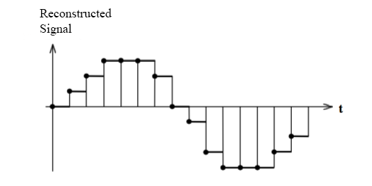
Reconstructed signal
Reconstruction of the digitalized signal using simple retention

Let's see now with more detail the process of reconstructing a signal. The simplest procedure will consist in simply obtaining a proportional value of the binary number of each sample using a digital analogue converter and keep it constant until a new sample arrives, which is usually when a new sample cycle starts, this process is named simple retention and that's the procedure used in the figure above.

Once the signal has been reconstructed, we must use a smoothing filter which in this case is a low pass filter that rounds the sharp edges that are a result of the simple retention. Such filter must have similar characteristics to the antialiasing filter that we had introduced for the digitalization process, this means it should have a very abrupt slope and eliminate almost entirely the frequencies over 20 kHz and it should allow the ones which are under 20 kHz to pass through completely. These kind of filters are complex and they are likely to introduce phase distortions. To solve this situation the concept of oversampling has been introduced.

Oversampling consists in interleaving the samples of the signal that are really obtained or stored, other "samples" that are calculated by interpolation using complex algorithms, thus an oversampling with a multiplier of 8 adds 7 interpolated samples of every real sample. The result is equivalent to a sample rate 8 times superior to the original. If fM =  44.1 kHz, then the new sample rate would be 352.8 kHz which can be eliminated with lowpass filters that are much simpler and with less effects over the phase and transients of the signal. Oversampling is used regularly today in compact disc players, which is possible because the speed of electronics is much higher than when this technology had just arrived.

Dithering 


When very low level signals are digitalized (near to the converter's resolution) digitalization noise turns into a distortion whose effect is more harmful than random noise. For example if a 100 Hz sine signal was digitalized whose amplitud would be less than one step, the signal we'd obtain after reconstruction would resemble more a square wave as shown in the figure below, and because of this it will have harmonics in 300 Hz, 500Hz, 700Hz, etc. If instead of one sine wave we would apply two or more we'd get an intermodulation distortion that would be really undesirable. 

Distortion created by sampling low level signals


One way of solving these inconveniences is to apply a small amount of random noise before sampling and digitalization. This noise, whose effective value is less than one step is known as dither. Dither has the side effect of worsening slightly the signal to noise ratio, from an auditive point of view the distortion is then transformed into a random noise that is more acceptable specially in those low levels.

Dither is also usually applied  in the requantization processes, which means you want to reduce the resolution of a signal that was recorded in 20 bits to 16 bits so we can dump it into a commercial format like a compact disc. If we just truncated the 20 bit data eliminating the least significant 4 bits, we would get similar inconveniences to the one described. In this case noise is generated digitally and is added before proceeding to truncate the bits.


Saturday, June 25, 2016

Digital Audio - Part 1 Introduction to Digital Audio

Digital Audio
Today digital audio tends to be used more than analogue audio as a method of storage. Records and cassette tapes continue to be used, but by a relatively small market. (Compare the prevalence of records 20 years ago to today.) Why is digital audio more prevalent? While there is some debate as to whether or not digital audio actually sounds better than analogue audio, digital audio is certainly easier to reproduce and to manipulate without loss of quality. Because of digital audio, it is much easier for both amateur and professional musicians today to produce studio-quality music.

Digital audio techniques has become relevant in the latest decades due to it's fundamental importance in the development of new technologies for audio generation, processing, storage and analysis. This has been possible thanks to the huge advances in microelectronics and it's application in the production of powerful and complex devices that are capable of handling and transforming sound with an increasing precision and speed the enormous amount of information contained in sounds.

One of the first consequences of the application of digital technology to audio was the development of very dependable audio storage systems that are unalterable and faithful. Another was the great boost to the development of electronic music instruments of great complexity and versatility. The third consequence was the development and application of techniques for the processing of the audio signal that allowed not only the improvement of processes that before were handled analogically, but also the introduction of new processes, we can find among them  a huge amount of effects such as delays, modulations, reverb, and specializations of amazing realism, whose analogue implementation would be too costly and destined to a much more restricted market.

The basic idea behind digital audio is to represent sound using numbers ("digital" comes from digit meaning number).  Before we start with the analysis we can see how this provides several advantages. In first place the problem of information alterability is eliminated. It is much easier to store a number than the physical magnitude that this number represents. For example if we wanted to store a 22.53 in dipstick we would be in serious trouble. The dilatation cause by temperature or any dust particle that sticks to it's extremes of simply wear from use could cause an error. This is valid for the length of a dipstick, it is even more valid for the magnetic field store in a recorded cassette.

In second place, there are algorithms (calculation methods) to achieve digitally not only the processing types used in traditional audio like amplification, mix, modulation, filtering, compression and expansion, etc. But also others like delays, sync, frequency displacement, sound generation using diverse procedures, etc. These algorithms can be implemented using a general purpose computer or in specific devices called Digital Signal Processors (DSP).

In third place, the replacement of analogue processors for their digital counterparts allows to avoid signal degradation due to analogue noise, something very convenient because analogue noise is hard to eliminate.

Bibliography: Federico Miyara (2003) Acústica y sistemas de sonido. UNR Editora
ISBN 950-673-196-9

Friday, June 24, 2016

Chiptune composition using Atari's POKEY Sound Chip


I made this tune using the classical sounds of the ATARI POKEY Sound Chip, I hope you like it. #8BitLove

Other Synthesis Methods - Part 2 Physical Modeling

Physical Modeling
In music, physical modeling refers to a sound synthesis technique which is based on models of the sound production mechanisms involved in musical instruments. The idea is to generate sound by reproducing how real musical instruments actually function and produce sound.


Physical modeling is a sound synthesis technique in which the waveform of the sound to be generated is calculated using a mathematical model that simulates a physical source of sound. Engineers created the model by simplifying the law of physics involved in sound generation. The parameters that can be found in this kind of synthesizer are of two kinds; some change the constants that describe the physical materials and dimensions of the instrument, while others are time-dependent functions that describe the player’s interaction with it. (e.g. how the instrument is played by rubbing or striking or opening and closing tone holes).

This approach may seem straightforward but is in fact very different from other techniques, such as FM, additive, subtractive and sampling, which could all be referred to as 'signal-based' methods because they attempt to reproduce the output signal from an instrument without worrying about how it was produced. A physical model is obtained from the laws of physics which describe how the world around us behaves. As in other fields of physics, a physical model is nothing else than a set of mathematical equations able to reproduce what can be measured experimentally.

In the case of a guitar for example, a physical model would reproduce how the pick moves the string away from its rest position; how the string vibrates once it is released; how the string vibration is transmitted to the soundboard through the bridge; and finally how the soundboard radiates sound which we can hear

With the development of computers, scientists began to find ways to implement these models as algorithms and program them in order to produce sound. This field of research became very active in the 80's but the situation was then very different from the one we know today. It then took literally hours of number crunching on the most powerful computers of that time to obtain just a few seconds of sound. That's far from real-time! Even listening to the sound samples was not that simple as sound cards were not very common back then.
So the key factor for physical modeling has really been the increase of the power of computers which now enables us to run in real-time sophisticated enough models that can reproduce the complexity of real musical instruments.

If one looks at the music industry, Yamaha was the first company to offer a synthesizer based on physical modeling. In the early nineties, they released the VL1 which implemented physical modeling algorithms on dedicated electronics. Tassman, released by AAS in 2000, was the first software synthesizer entirely based on physical modeling.

This technology is definitely not limited to acoustic instruments. One can apply exactly the same approach to electronic instruments such as vintage synthesizers. In these cases, the computer solves in real-time models of how electric circuits used in vintage synths, filters, tube amps and effect processors functionned and behaved. The benefits are the same as for acoustic instruments. Indeed the models can reproduce the complex behavior of these electronic components resulting in sound as lively and rich as that of the hardware units.

Bibliography:

AAS - Tech Talk - Physical modeling. (n.d.). Retrieved June 24, 2016, from
https://www.applied-acoustics.com/techtalk/physicalmodeling/

Ness - Physical Modeling Synthesis (n.d.) Retrieved June 24, 2016 from
http://www.ness-music.eu/overview/physical-modeling-synthesis

Gregory Taylor - Physical Modeling Synthesis for Max Users: A Primer Published October 10, 2012, Retrieved June 24, 2016 from
https://cycling74.com/2012/10/09/physical-modeling-synthesis-for-max-users-a-primer/#.V20bE1fmpuU

Hiller, L.; Ruiz, P. (1971). "Synthesizing Musical Sounds by Solving the Wave Equation for Vibrating Objects". Journal of the Audio Engineering Society.

Karplus, K.; Strong, A. (1983). "Digital synthesis of plucked string and drum timbres". Computer Music Journal (Computer Music Journal, Vol. 7, No. 2) 7 (2): 43–55. doi:10.2307/3680062. JSTOR 3680062.

Julius O. Smith III (December 2010). Physical Audio Signal Processing.
Cadoz, C.; Luciani A; Florens JL (1993). "CORDIS-ANIMA : a Modeling and Simulation System for Sound and Image Synthesis: The General Formalism". Computer Music Journal (Computer Music Journal, MIT Press 1993, Vol. 17, No. 1) 17/1 (1).

Thursday, June 23, 2016

Other synthesis methods Part 1 - Frequency Modulation (FM)


Yamaha DX7 The most famous synthesizer of the 1980s. Its electric piano became a standard sound in ballads and "smooth jazz" genres.  Its bass was the standard bass sound, typically played in bouncy octaves.  Its crystalline timbres were such a departure from the world of analog, that this synth was a super-hit for Yamaha in 1983, and spanned a long family of FM-based products.

FM is a form of synthesizer developed in the early 1970s by Dr John Chowning of Stanford University, then later developed further by Yamaha, leading to the release of the now-legendary DX7 synthesizer: a popular source of bass sounds for numerous dance musicians.

Unlike analogue, FM synthesizers produce sound by using operators, which are very similar to oscillators in an analogue synthesiser but can only produce simple sine waves. Sounds are generated by using the output of the first operator to modulate the pitch of the second, thereby introducing harmonics Like an analogue synthesizer, each FM voice requires a minimum of two oscillators in order to create a basic sound, but because FM only produces sine waves the timbre produced from just one carrier and modulator isn't very rich in harmonics

FM synthesis is based on two key things – a ‘modulator’ oscillator, and a ‘carrier’ oscillator. These oscillators usually both use a sine waveform, and from this the modulator oscillator works just like an LFO – because it modulates the frequency/pitch of the carrier oscillator. You can try this yourself on a normal subtractive synthesizer, by setting up a sine wave oscillator and an LFO, and using the LFO to modulate the pitch of the oscillator – as you increase the rate of the LFO, the sound becomes non-harmonic. Note that in FM synthesis, the word ‘oscillator’ is often replaced with the term ‘operator’. As you change the modulation of the carrier operator, the frequency of the carrier will constantly move up and down depending on how the modulator is set up (e.g. it’s depth and rate), and in doing this different harmonics are created (called ‘sidebands’), because these harmonics surround the carrier frequency depending on how it is modulated.

Because of the somewhat lifeless sound of the operators, FM synthesizers tend to include somewhere around 4-8 operators on a synth to spice things up. These extra operators can be routed in all sorts of different and interesting ways, called ‘algorithms’. For example, with the addition of an extra modulator operator, we can arrange the operators so that they go ‘’modulator 1’ & ‘modulator 2’ go into the carrier’, or ‘modulator 1 goes into modulator 2, which goes into the carrier’ – this being more complicated and creating a new waveform. Therefore, using many operators can produce unique and lifelike sounds unachievable with other types of sound synthesis.

Frequency Modulation
In telecommunications and signal processing, frequency modulation (FM) is the encoding of information in a carrier wave by varying the instantaneous frequency of the wave. This contrasts with amplitude modulation, in which the amplitude of the carrier wave varies, while the frequency remains constant.

Due to the nature of FM, many of the timbres created are quite metallic and digital in character, particularly when compared to the warmth generated by the drifting of analogue oscillators. Also due to the digital nature of FM synthesizer the facia generally contains few real time controllers. Instead, many numerous buttons adorn the front panel forcing you to navigate and adjust any parameters through a small LCD display.

Notably, although both FM and analogue synthesisers were originally used to reproduce realistic instruments, neither can fabricate truly realistic timbres. If the goal of the synthesiser system is to recreate the sound of an existing instrument, this can generally be accomplished more accurately using digital sample based techniques.

if you want to know more about synthesis techniques please read. Rick Snoman's Dance Music Manual (Second Edition) Tools, Toys and Techniques.


Wednesday, June 22, 2016

The science of Synthesis Part 8 - Modifiers

LFO
Most synthesizers also offer additional tools for manipulating sound in the form of modulation sources and destinations. Using these tools, the response or movement of one parameter can be used to modify another totally independent parameter, hence the name 'modifiers'

The number of modifiers available, along with the destinations they can affect is entirely dependent on the synthesiser. Many synthesisers feature a number of envelope generators that allow the action of other parameters alongside the amplifier to be controlled.

For example in many synthesizers feature a number of envelope generators that allow the action of other parameters alongside the amplifier to be controlled.

For example, in many synthesisers, an envelope may be used to modify the filter's action and by doing so you can make tonal changes to the note while it plays. A typical example of this is the squelchy bass sound used in most dance music. By having a zero attack, short decay and zero sustain level on the envelope generator, a sound that starts with the filter wide one before quickly sweeping down to fully closed is produced. This movement is archetypal to most forms of dance music but does not necessarily have to be produced by envelopes. Instead, some synthesisers offer one-shot low-frequency oscillators (LFOs) which can be used in the envelope's place. For instance by using a triangle waveform LFO to modulate the amp, there is a slow rise in volume before a snowdrop again.

Low Frequency Oscillator


LFO's produce output frequencies in much the same way as VCOs. The difference is that a VCO produces an audible frequency (within the 20Hz-20kHz range) while an LFO produces a signal with a relatively low frequency that is inaudible to the human ear (in the range of 1-10Hz).

The waveforms an LFO can utilise depend entirely upon the synthesizer in question, but they commonly employ sine, saw, triangle, square and sample and hold waveforms. The sample and hold waveform is usually constructed with a randomly generated noise waveform that momentarily freezes every few samples before beginning again.

LFO's should not be underestimated because they can be used to modulate other parameters known as  'destination', to introduce additional movement into a sound. For instance, if an LFO is set to a relatively high frequency, say 5Hz, to modulate the pitch of a VCO, the pitch of the oscillator will rise and fall according to the speed and share of the LFO waveform and an effect similar to that of vibrato is generated. If a sine wave is used for the LFO, then it will essentially create an effect similar to that of a wailing police siren. Alternatively, if this same LFO is used to modulate the filter cut-off, then the filter will open and close at a speed determined by the LFO, while if it were used to modulate an oscillator's volume, it would rise and fall in volume recreating a tremolo effect.

This means that an LFO must have an amount control (sometimes known as depth) for varying how much the LFO's waveform augments the destination  rate control to control the speed of the LFO's waveform cycles, and a fade-in control in some. The fade-in control adjusts how quickly the LFO begins to affect the waveform after a key has ben pressed. An example of this is shown in figure the figure below.

LFO fade in
LFO fade-in

The LFO on more capable synthesizers may also have access to it's own envelope. This gives control of the LFO's performance over a specified time period, allowing it not only to fade in after a key has been pressed but also to decay, sustain, and fade away gradually. It is worth noting, however, that the destinations an LFO can modulate are entirely dependent on the synthesiser being used. Some synthesizers may only allow LFOs to modulate the oscillator's pitch and the filter, while others may offer multiple demonstrations and more LFOs. Obviously the more LFOs and destinations that are available, the more creative options you will have at your disposal.

If required, further modulation can be applied with an attached controller keyboard or the synthesizer itself in the form of two modulation wheels. The first, pitch bend, is hard-wired and provides a convenient method of applying a modulating CV to the oscillator(s). By pushing the wheel away from you, you can bend the pitch (i.e. frequency) of the oscillator up. Similarly, you can bend the pitch down by pulling the wheel towards you. This wheel is normally spring loaded to return to the center position, where no bend is applied, if you let go of it, and is commonly used in synthesisers solos to give additional expression. The second wheel, modulation, is freely assignable and offers a convenient method of controlling any on-board parameters, such as the level of the LFO signal sent to the oscillator, filter or VCA or to control the filter cutoff directly. Again, whether this wheel is assignable will depend on the manufacturer of the synthesiser.

On some synthesisers the wheels are hard coded to only allow oscillator modulation (for a vibrato effect), while some others do not have a separate modulation wheel and instead the pitch bend lever can be pushed forward to produce LFO modulation.

Practical applications


While there are other forms of synthesis - which will be discussed in later posts - most synthesisers use in the production of dance music are of an analogue/subtractive nature therefore it's vital that the users grasps the concepts behind the elements of subtractive synthesis and how they can work together to produce a final timbre. With this in mind, it is sensible to experiment with a short example to aid in the undertaking of the components.

Using the synthesiser of your choice, clear all the current settings so that you start from nothing. On many synthesisers this is known as 'initialising a patch', so it may be a button labelled 'init', 'init patch' or similar. 

Begin by pressing and holding C3 on your synthesiser, or alternatively controlling the synthesiser via MIDI programming in a continual note. If not, place something heavy on C3. The whole purpose of this exercise is to hear how the sound develops, as you begin to modify the controls of the synthesiser, so the note needs to play more continually.

Select sawtooth waves for two oscillators, if there is a third oscillator that you cannot turn off, choose a triangle for this third oscillator. Next, detune one sawtooth from the other until the timbre begins to thicken. This is a tutorial to grasp the concept of synthesis, so keep detuning until you hear the oscillators separate from one another and then move back until they become one again and the timbre is thickened out. Generally speaking, detuning of 3 cents should be ample but do not be afraid to experiment - this is a learning process. If you are using a triangle wave, detune this against the two saws and listen to the results, Once you have a timbre you feel you can work with, move onto the next step.

Find the VCA envelope and start experimenting. You will need to release C3 and then press it again so you can hear the effect that the envelope is having on the timbre. Experiment with these envelopes until you have a good grasp on how they can adjust the shape of a timbre; once you are happy you have an understanding, apply a fast attack with a short decay, medium sustain and a long release. As before, for this next step you will need to keep C3 depressed.

Find the filter section, and experiment with the filter settings. Start by using a high-pass filter with the resonance set around midway and slowly turn the filter cut-off control. Note how the filter sweeps through the sound, removing the lower frequencies first, slowly progressing to the higher frequencies. Also experiment with the resonance by rotating it to move upwards and downwards and note how this affects the timbre. Do the same with the notch and band pass, etc. (if the synthesiser has these available) before finally moving to the low pass. Set the low-pass filter quite low, along with a low-resonance setting - you should now have a static buzzing timbre.

The timbre is quite monotonous, so use the filter envelope to inject some life into the sound. This envelope works on exactly the same principles as the VCA, with the exception that it will control the filter's movement. Set the filter's envelope to a long attack and decay, but use a short release and no sustain and set the filter envelope to maximum positive modulation. If the synthesiser has a filter key follow, use this as it will track the pitch of the note being played and adjust itself. Now try depressing C3 to hear how the filter envelope controls the filter, essentially sweeping through the frequencies as the note plays.

Finally, to add some excitement to the timbre, find the LFO section. Generally, the FLO will have a rotary control to adjust the rate (speed), a selector switch to chose the LFO waveform, a depth control and a modulation destination. Choose a triangle wave for the LFO waveform, Hold down C3 on the synthesiser's keyboard, turn the LFO depth control up to maximum and set the LFO destination to pitch. As before, hold down the C3 key and slowly rotate the LFO rate (speed) to hear the results. If you have access to a second LFO, try modulating the filtre cut-off with a square wave LFO, set the LFO depth to maximum and experiment with the LFO rate again.

Here concludes the seventh part of this post, if you want to know more about acoustic science please read. Rick Snoman's Dance Music Manual (Second Edition) Tools, Toys and Techniques.

Monday, June 20, 2016

The science of synthesis part 7 - Voltage Controlled Amplifiers (VCA)

Anagogic Synth Amplifier
An amplifier, electronic amplifier or (informally) amp is an electronic component that can increase the power of a signal. An amplifier functions by taking power from a power supply and controlling the output to match the input signal shape but with a larger amplitude. In this sense, an amplifier modulates the output of the power supply based upon the properties of the input signal. An amplifier is effectively the opposite of an attenuator: while an amplifier provides gain, an attenuator provides loss.

Once the filters have sculpted a sound, the signal then moves into the final stage of synthesiser. The amplifier. When a key is pressed, rather than the volume rising immediately to its maximum and falling to zero when released, an 'envelope generator' is employed to emulate the nuances of real instruments.


The ADSR envelope
The ADSR envelope

Few, if any, acoustic instruments start and stop immediately. It takes a fine amount of time for the sound to reach it's amplitude and then decay away to silence again; thus, the 'envelope generator' - a feature of all synthesisers - can be used to shape the volume with respect to time. This allows you to control whether a sound starts instantly the moment a key is pressed or builds up gradually and how the sound dies away (quickly or slowly) when the key is released.

These controls usually comprise four sections called attack, decay, sustain, and release (ADSR), each of which determines the shaping that occurs at certain points during the length of a note. An example of this is shown in Figure 1.20


  • Attack: The attack control determines how the note starts from the point when the key is pressed and the period of time it takes for the sound to go from silence to full volume. If the period set is quite long, the sound will 'fade in', as if you are slowly turning up a volume knob. If the period set is short, the sound will start the instant a key is pressed. Most instruments utilise a very short attack time.
  • Decay: Immediately after a note has begun it may initially decay in volume. For instance, a piano note starts with a very loud, percussive part but then drops quickly to a lower volume while the note sustains as the key is held down. The time the note takes to fade from the initial peak at the attack stage to the sustain level is known as the 'decay time'.
  • Sustain: The sustain period occurs after the initial attack and decay periods and determines the volume of the note while the key is held down. This means that if the sustain level is set to maximum, any decay period will be ineffective because at the attack stage the volume is at maximum so there is no level to decay down to. Conversely, if the sustain level were set to zero, the sound peaks following the attack period and will fade to nothing even if you continue to hold down th key. In this instance, the decay time determines how quickly the sound decays down to silence.
  • Release: The release period is the time it takes for the sound to fade from the sustain level to silence after the key has been released. If this is set to zero, the sound will stop the instant the key is released, while if a high value is set the note will continue to sound, fading away as the key is released.


Although ADSR envelopes are the most common, there are some subtle variations such as attack-release (AR), time-attack-delay-sustain-release (TADSR), and attack-delay-sustain-time-release. (ADSTR). Because there are no decay or sustain elements contained in most drum timbres, AR envelopes are often used on drum synthesisers. They can also appear on more economical synthesisers simply because the AR parameters are regarded as having the most significant effect on a sound, making them a basic requirement. Both TADSR and ADSTR envelopes are usually found on more expensive synthesisers. With the additional period, T (time), in TADSR for instance, it is possible to set the amount of time that passes before the attack stage is reached. (See figure below)


TADSR Envelope
The TADSR Envelope


It's also important to note that not all envelopes offer linear transitions, meaning that the attack, decay and release stages will not necessarily consist entirely of a straight line as it is shown in the following figure On some synthesisers these stages may be concave or convos, while other synthesisers may allow you to state whether the envelope stages should be linear, concave or convex. The differences between the linear and the exponential envelopes are shown in Figure below.


Linear and exponential envelopes


Here concludes the seventh part of this post, if you want to know more about acoustic science please read. Rick Snoman's Dance Music Manual (Second Edition) Tools, Toys and Techniques.

Saturday, June 11, 2016

The Science of Synthesis - Part 6 - Voltage Controlled Filters

Voltage Controlled Filter
A voltage-controlled filter (VCF) is a processor, a filter whose operating characteristics (primarily cutoff frequency) can be controlled by means of a control voltage applied to control inputs. It can be considered to be a frequency-dependent amplifier. Although popularly known for their use in analog music synthesizers, in general, they have other applications in military and industrial electronics.

Following the oscillator's mixer section are the filters for sculpting the previously created signal. In the synthesizer world, if the oscillator's signal is thought of as a piece of wood that is yet to be carved, the filters are the hammer and chisels that are used to shape it. Filters are used to chip away pieces of the original signal until a rough image of the required sound remains.

This makes filters the most vital element of any subtractive synthesizer because if the available filters, are of poor quality, few sound sculpting options will be available and it will be impossible to create the sound you require. Indeed the choice of filters combined with the oscillators waveforms is often the reason why specific synthesizers must be used to recreate certain 'classic' dance timbres.

The most common filter used in basic subtractive synthesizers is a low-pass filter. This is used to remove frequencies above a defined cut-off point. The effect is progressive, meaning that more frequencies are removed from a sound, the further the control is reduced, starting with the higher harmonics and gradually moving to the lowest. If this filter cut-off point is recused far enough, all harmonics above the fundamental can be removed leaving just the fundamental frequency. While it may appear senseless to create a bright sound with oscillators only to remove them later with a filter, there are several reasons why you may wish to do this.


  • Using a variable filter on a bright sounds allows you to determine the color of the sound much more precisely than if you tried to create the same effect using oscillators alone.
  • This method enables you to employ real-time movement of a sound.


This latter movement is an essential aspect of sound design because we naturally expect dynamic movement of sound throughout the length of the note.

Using our previous example of a piano string being struck, the initial sound is very bright, becoming duller as it dies away. This effect can be simulated by opening the filter as the note starts and then gradually sweeping the cut-off frequency down to create the effect of the note dying away.

Notably, when using this effect, frequencies that lie above the cut-off point are not attenuated at right angles to the cut-off frequency; therefore, the rate at which they die away will depend on the transition period. This is why different filters that essentially perform the same function can make beautiful sweeps, whist others can produce quite uneventful results.

Action of a low-pass filter

When a cut-off point is designated, small quantities of the harmonics that lie above this point are not removed completely and are instead attenuated by a certain degree. The degree of attenuation is dependent on the transition band of the filter being used. The gradient of this transition is important because it defines the sound of any one particular filter. If the slope is steep, the filter is said to be 'sharp0 and if the slope is more gradual the filter is said to be 'soft.' To fully understand the action of this transition, some prior knowledge of the electronics involved in analogue synthesizer is required.

When the first analogue-synthesizers appeared in the 1960s, different voltages were used to control both the oscillators and the filters. Any harmonics produced by the oscillators could be removed gradually by physically manipulating the electrical current. This was achieved using a resistor (to reduce the voltage) and a capacitor (RC) circuit. Because a single RC circuit produces a 6dB transition, the attenuation increases by 6dB every time a frequency is doubled.

One RC element creates a 6dB per octave 1-pole filter that is very similar to the gentle slope created by a mixing desks EQ. Consequently, manufacturers soon implemented additional RC elements into their designs to create 2-pole filters, which attenuated 12dB per octave, and 4-pole filters, to provide 24dB per octave attenuation. Because 4-poles filters attenuate 24dB per octave making substantial changes to the sound, they tend to sound more synthesized than sounds create by a 2-pole filter; so it's important to decide which transition period is best suited for the sound. For example, if a 24 dB filter is used to sweep a pad, it will result in strong attenuation throughout the sweep, while a 12 dB will create a more natural flowing movement.

12 dB and 24dB slopes
The difference between 12dB and 24dB slopes

Although low-pass filters are the most commonly used type, there are numerous variations including high pass, band pass, notch and comb. These utilize the same transition periods as the low-pass filter, but each has a wide different effect on the sound.


High-pass filter
Action of the high pass filter

A high-pass filter has the opposite effect to a low-pass filter, first removing the low frequencies from the sound and gradually moving towards the highest. This is less useful than the low-pass filter because it effectively removes the fundamental frequency of the sound, leaving only the fizzy harmonic overtones. Because of this, high-pass filters are rarely used in the create of instruments and are predominantly used to create effervescent sound effects or bright timbres that can be laid over the top of another lowness sound to increase the harmonic content.


Action of the band select filter
Action of the Band select filter

The typical euphoric trance leads are a good example of this, as they are often created from a tone with the fundamental overlaid with numerous other tones that have been created using a high-pass filter. This prevents the timbre from becoming too muddy as a consequence of stacking together fundamental frequencies. In both remixing and dance music, it's commonplace to run a high.pass filter over an entire mix to eliminate the lower frequencies, creating an effect similar to a transistor radio or a telephone. By reducing the cut-off control, gradually or immediately, the track morphs from a thin sound to a fatter one, which can produce a dramatic effect in the right context.

If high- and low-pass filters are connected in series, then it's possible to create a band-pass, or band-select filter. These permit a set of frequencies to pass unaltered through the filter while the frequencies either side of the two filters are attenuated. The frequencies that pass through unaltered are known as the 'bandwidth' or the 'band pass' of the filter, and clearly, if the low pass is set to attenuate a range of frequencies that are above the current high-pass setting, no frequencies will pass through and no sound is produced.

Band-pass filters, like high-pass filters, are often used to create timbres consisting of fizzy harmonics (Figure 1.15). They can also be used to determine the frequency content of a waveform, as by sweeping through the frequencies each individual harmonic can be heard. Because this type of filter frequently removes the fundamental, it is often used as the basis of sound effects or lo-fi and trip-hop timbres or to create very thin sounds that will form the basis of sound effects.

Although band-pass filters can be used to thin a sound, they should not be confused with band-reset filters, which can be used for a similar purpose. Band-reject filters, often referred to as notch filters, attenuate a selected range of frequencies effectively creating a notch in the sound - hence the name - and usually leave the fundamentals unaffected. This type of filter is handy for scooping out frequencies, thinning out a sound while leaving the fundamentals intact, making them useful for creating timbres that contain a discernible pitch but do not have a high level of harmonic content.

Action of the notch filter

One final form of the filter is the comb filter. With these, some of the samples entering the filter are delayed in time and the output is the fed back in the filter to be reprocessed to produces the results, effectively creating a comb appearance, hence the name. Using this method, sounds can be tuned, to amplify or reduce harmonics based on the length of the delay and the sample rate, making it useful for creating complex sounding timbres that cannot be accomplished any other way. Because of the way they operate, however is rare to find these featured on a synthesizer and are usually available only as a third-party effect.

Action of the comb filter

As an example, if a 1kHZ signal is put through the filter with a 1ms delay, the signal will result in phase because 1ms is coincident with the inputted signal, equalling one. However, if a 500 Hz signal with a 1ms delay were used instead it would be half of the period length and so it would be shifted out of phase by 180°, resulting in a zero. It's this constructive and deconstructive period that creates the continual bump then dip in harmonics, resulting in a comb like appearance when represented graphically, as in Figure 1.17. This method applies to all frequencies, with integer multiples of 1 kHZ producing ones and odd multiples of 500 Hz (1.5, 2.5, 3.5 kHz etc.) producing zeros. The effect of using this filter can at best be described as highly resonant, and forms the basis of flanger effects; therefore, it's use is commonly limited to sound design rather than the more basic sound sculpting.

One final element of sound manipulation in a synthesizer's filter section is the resonance control. Also referred to as peak, this refers to the amount of the output of the filter that is fed back directly into the input, emphasizing any frequencies that are situated around the cut-off frequency. This has a similar effect to employing a band-pass filter at the cut-off point, effectively creating a peak. Although this also affects the filter's transition period, it is more noticeable at the actual cut-off frequency than anywhere else. Indeed, as you sweep through the cut-off range, the resonance follows the curve, continually peaking at the cut-off point. In terms of the final sound, increasing the resonance makes the filter sound more dramatic and is particularly effective when used in conjunction with low-pass filter sweeps.

Resonance
The effects of resonance

On many analogue and DSP-analogue-modelled synthesizers, if the resonance is turned up high enough it will fed back on itself. As more and more of the signal is fed back, the signal is exaggerated until the filter breaks into self-oscillation. This produces a sine wave with a frequency equal to that of the set cut-off point and is often a purer sine wave than that produced by the oscillators. Because of this, self-oscillating filters are commonly used to create deep, powerful sub-basses that are particularly suited to the drum 'n' bass and rap genres.

Notably, some filters may also feature a saturation parameter which essentially overdrives the filters. If applied heavily, this can be used to create distortion effects, but more often it's used to thicken out timbres and add even more harmonics and partials to the signal to create rich sounding leads or basses.

The keyboard's pitch can also be closely related to the action of the filters, using a method known as pitch tracking, keyboard scaling or more frequently 'key follow'. On many synthesizers the depth of this parameter is adjustable, allowing you to determine how much or how little the filter should follow the pitch.

The effect of filter key follow

When this parameter is set to it's neutral state (neither negative nor positive), as a note is played on the keyboard the cut-off frequency tracks the pitch and each note is subjected to the same level of filtering. If this is used on a low-pass filter, for example, the filter setting remains fixed, so as progressively higher notes are played fewer and fewer harmonics will be present in the sound, making the timbre of the higher notes mellower than that of the lower note. If they key follow parameter is set to positive, the higher notes will have a higher cut-off hand, the key follow parameter is set to negative, the higher notes will lower the cut-off frequency, making the high notes even mellower than when key follow is set to it's neutral state. Key follow is useful for recreating real instruments such as brass, where the higher notes are often mellower than the lower notes, and is also useful on complex bass lines that jump over an octave, adding further variation to a rhythm.

Here concludes the sixth part of this post, if you want to know more about acoustic science please read. Rick Snoman's Dance Music Manual (Second Edition) Tools, Toys and Techniques.